ac unit capacitor function

Role of Capacitor in AC Circuits: In an AC circuit, capacitor reverses its charges as the current alternates and produces a lagging voltage (in other words, capacitor provides leading current in AC circuits and networks) Role and Performance of Capacitor in DC Circuit In a DC Circuit, the capacitor once charged with the applied voltage acts as an open switch. This type of capacitor is sensitive about their polarity and can be only used in DC systems and networks. Polar Capacitors don’t work in the AC system, because of the reversal of polarity after each half cycle in AC supply. There are lots of advantages of power factor improvement. In a three phase power systems, capacitor bank is used to supply reactive power to the load and hence improve the power factor of the system. Capacitor bank is installed after a precise calculation. Basically, it delivers the reactive power which was previously traveled from the power system, hence it reduces the losses and improves the efficiency of the system.

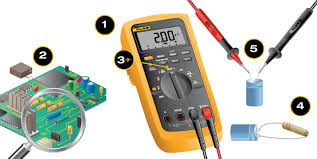
Enter your email address: EasyEDA: A Powerful Free Circuit, Simulation & PCB Design ToolUser ReviewedHow to Test a Capacitor Five Methods:Using a Digital Multimeter With Capacitance SettingUsing a Digital Multimeter Without Capacitance SettingUsing an Analog MultimeterTesting a Capacitor With a VoltmeterShorting the Capacitor TerminalCommunity Q&A Capacitors are voltage storage devices used in electronic circuits, such as those found in heating and air conditioning fan motors and compressors. Capacitors come in 2 main types: electrolytic, which are used with vacuum tube and transistor power supplies, and non-electrolytic, which are used to regulate direct current surges. Electrolytic capacitors can fail by discharging too much current or by running out of electrolyte and being unable to hold a charge. Non-electrolytic capacitors most often fail by leaking their stored charge.[1] There are several ways to test a capacitor to see if it still functions as it should. Disconnect the capacitor from the circuit it is part of.

Read the capacitance value on the outside of the capacitor. Set your multimeter to its capacitance setting. Connect the multimeter leads to the capacitor terminals. Connect the positive (red) multimeter lead to the capacitor anode lead and the negative (black) lead to the capacitor cathode lead.
ac unit running in reverse(On most capacitors, especially electrolytic capacitors, the anode lead is longer than the cathode lead.)
hotel heater and ac unit Check the multimeter reading.
air handling units catalogueIf the capacitance reading on the multimeter is close to the value printed on the capacitor itself, the capacitor is good. If it’s significantly less than the value printed on the capacitor, or zero, the capacitor is dead. Disconnect the capacitor from its circuit.

Set your multimeter to its resistance setting. This setting may be marked with the word “OHM” (the unit for resistance) or the Greek letter omega (Ω), the abbreviation for ohm. If your unit has an adjustable resistance range, set the range to 1000 ohm = 1K or higher. Connect the multimeter leads to the capacitor terminals. Observe the multimeter reading. Disconnect and reconnect the capacitor several times. You should see the same results as on the first test. If you do, the capacitor is good. If, however, the resistance value does not change on any of the tests, the capacitor is dead. Set your multimeter to its resistance stetting.Analog multimeters use a needle to display their results. How the needle behaves determines whether or not the capacitor is good. If the needle initially shows a low resistance value then gradually moves to the right, the capacitor is good. If the needle shows a low resistance value and doesn’t move, the capacitor has been shorted out.
You’ll need to replace it. If the needle shows no resistance value and doesn’t move or a high value and doesn’t move, the capacitor is an open capacitor (dead). Disconnect the capacitor from its circuit. You may, if you wish, disconnect only 1 of the 2 leads from the circuit. Check the capacitor’s voltage rating. Charge the capacitor with a known voltage less than, but close to, its rated voltage. For a 25V capacitor, you could use a voltage of 9 volts, while for a 600V capacitor, you should use a voltage of at least 400 volts. Let the capacitor charge for a few seconds. Be sure to connect the positive (red) lead from the voltage source to the positive (longer) capacitor terminal and the negative (black) lead to the negative (shorter) terminal. The greater the discrepancy between the capacitor’s voltage rating and the voltage you’re charging it with, the longer it will take to charge. Generally, the higher voltage of the power supply you have access to, the higher the voltage ratings of the capacitors you can test with ease.

Set your voltmeter to read DC voltage (if it’s capable of reading both AC and DC). Connect the voltmeter leads to the capacitor. Note the initial voltage reading. This should be close to the voltage you supplied the capacitor with. If it isn’t, the capacitor is no good. The capacitor will discharge its voltage into the voltmeter, causing its reading to drop back to zero the longer you have the leads connected. Only if the initial reading is much lower than the expected voltage should you be concerned. Connect leads to the capacitor. Connect the leads to a power supply for a short time. Disconnect the leads from the power supply. Short the capacitor terminals. Look at the spark created when you shorted the terminal. The possible spark will give you an indication of the capacity of the capacitor. This method will only work with capacitors that can hold enough energy to produce a spark when shorted. This method is not recommended because it only can be used to determine if the capacitor can hold a charge, capable of sparking when shorted, or not.
It can not be used to check if the capacity of the capacitor is within the specifications. Using this method on larger capacitors could result in serious injury or even death! Non-electrolytic capacitors generally are not polarized. When testing these capacitors, you can connect the leads from the voltmeter, multimeter, or power supply to either capacitor terminal. Non-electrolytic capacitors are subdivided by the types of materials they are made of -- ceramic, mica, paper, or plastic – with the plastic capacitors further subdivided by the type of plastic. Capacitors used in heating and air conditioning systems are subdivided by purpose into 2 types. Run capacitors maintain constant voltage to the fan motors and compressors in furnaces, air conditioners, and heat pumps. Start capacitors are used in units with higher-torque motors in some heat pumps and air conditioners to provide the extra energy needed at startup. Electrolytic capacitors usually have 20% tolerance.