ac unit wiring diagram

Basics of Bus Air Conditioning Trans/Air’s desire is to make this website as useful as possible for any type of customer. If for any reason you are unable to find the document you require, please feel free to contact us for personalized assistance. Note: Electrical and Piping Diagrams published here are listed by Trans/Air drawing number (part number). This listing, which includes Trans/Air's most widely purchased wiring and piping schematics is, by no means, intended to be all-inclusive. Prior to using any of these drawings, make certain it is the correct revision for your application. Please contact Trans/Air directly if you do not know which drawing number (part number) or revision you need or if you require technical assistance. First, You must accept the Wiring Diagrams Disclaimer at the bottom of this section (by reading, then clicking on the "Accept" button) This material is for professional use only and is intended to be used only as

reference material by licensed contractors when installing or servicing Reznor equipment. Nortek Global HVAC/Reznor does not endorse any field changes to factory wiring schemes. Also note that certain field modifications may occur to accommodate the use of otherAll servicing of product should be performed by a licensed contractor according to local and national code requirements. All material in this site is protected under copyright laws. Any and all use or reproduction other than for repair/installation of Reznor products is expressly forbidden. AutoCad® Format (DWG Files) You will need to have AutoCad or Autodesk View installed on your computer. If you do not have Autodesk View, follow these steps: To view the wiring diagrams download and install the free version of Voloview Express from Autodesk. note - this takes a lot of RAM to run (at least 32 meg). After installing Autodesk View you can automatically open drawings from the web site by

simply clicking on the drawing and choosing 'Open' after clicking on the link in your browser (this will work in newer versions of Internet Explorer and Netscape Navigator). Printing on 8.5" x 11" Paper After you've opened the drawing, if you'd like to print the entire drawing, you'll find it beneficial to print in landscape mode. First, you need to rotate the drawing. This is done by choosing View, Rotate, Left from the menu bar. Adobe Acrobat® Format (PDF Files) You will need to have Adobe Acrobat Reader installed on your computer. If you do not have Acrobat Reader, follow these steps: Installing Adobe Acrobat® Reader To view the wiring diagrams directly in your browser for reading or printing a PDF file format, you can install the free version of Acrobat Reader from Adobe. Go to Adobe Products by clicking the 'Get Acrobat Reader' Image below. After installing Acrobat Reader you can automatically open drawings from the web site by

simply clicking on the drawing in your browser. After opening the PDF file, you can Click on the Printer Icon in the Acrobat Reader Toolbar and make sure to Check the Box for 'Shrink Oversized pages to paper size.' Wiring diagrams for all new products are regularly added to our web site.
air conditioning units for listed buildings diagrams for older units are added periodically.
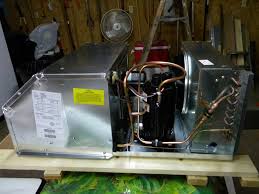
insulate ac window unitIf you can not find the
hvac unit outside fan not running wiring diagram you need, please contact us.Please try the following: If you typed the page address in the Address bar, make sure that it is spelled correctly. home page, and then look for links to the information you want. Click the Back button to try another link.

HTTP 404 - File not found Technical Information (for support personnel)Home / GY6 Electricals / GY6 150cc Ignition Troubleshooting Guide: No Spark? This guide covers almost any of the 150cc buggies, scooters, or ATV’s with the standard “AC” CDI setup. The first version was downloaded over and we’re happy that this information continues to help so many people! Don’t want to hassle with the electrical system? Due to frequent requests from readers of this guide wanting to avoid hacking into their electricals to find the problem, we’ve put together a kit with all of the electrical parts covered here to shotgun the most common “no spark” problems all at once. Instead of struggling with a multimeter for hours, you can now plug in the parts and be done. Recommended: Ignition Tune Up Kit Reliable vetted parts picked by the writers of this guide. Will fix spark, or your money back. Getting started: How it all works The 150cc GY6 ignition system is fairly easy to troubleshoot in the case of malfunction.
There are 4 major components that work together to produce spark, if any of these are defective spark will be lost. What we will be doing here is troubleshooting these ignition parts starting at the source, and working towards the spark plug. Stator (6th winding and trigger pickup module) To diagnose your ignition system, you will need to do each of the steps in this article, in sequence. Before getting started, take a look at this diagram. Although there are many differences in wiring between models, most GY6 ignition systems work the same as shown in this illustration. You’ll want to come back to this for reference throughout the guide. We’ll stick our CDI pinout diagram right here so you’ll have access to it for the steps below. FIRST STEP: BYPASS YOUR SWITCHES A very common cause of no spark is a defective ignition or kill switch. Before beginning to troubleshoot ignition problems, it is best to bypass the switches. How to bypass your switches

Create a jumper wire from pin #4 directly to a good grounding spot on the engine. Being very careful not to deform or break the pin, remove the #5 wire from the CDI plug at the harness. This can be done with a sharp narrow tool like an ice pick or stiff paper clip. Looking from the front of the plug, you will see small metal tabs on each pin which secure them to the plug. Push the tab down and the pin will release. Don’t use force here. Depending on your stator type, you have either 6, 8, or 11 windings. Of these windings, one is dedicated to supplying the CDI with ignition power. This winding is usually wrapped in white cloth material and sealed over with clear epoxy. A simple type of crankshaft position sensor. Sends a signal to the CDI to let it know when to send fire to the plug. Set your multimeter to read in VOLTS “AC”. Locate and disconnect the Black/Red and Blue/Yellow wires coming from the stator, where they plug into the main engine harness.

(These are both bullet-style connectors) While cranking the engine, use a multimeter to check for voltage coming from the Red/Black (CDI power wire) and the Blue/Yellow (trigger wire) coming from stator. Place the black lead of multimeter on a metal surface of the engine while using the red lead on the tips of the wires. There should be between 20vAC ~ 100vAC coming from the CDI power wire (Black/Red), although much lower voltages will still be able to produce spark. There should be at least 0.05vAC coming from the trigger wire (Blue/Yellow). Write the voltages down and continue to the next step. Stator output: 20vAC minimum Trigger output: 0.01vAC minimum STEP 2: THE CDI UNIT The CDI Unit is powered by the AC current coming from the wrapped stator winding. This current is stored in a capacitor within the CDI unit. When a signal is received by the trigger pickup passing over the flywheel magnet, the CDI will discharge the stored energy into the wires leading to the ignition coil.

Ensure your multimeter is set to read in VOLTS “AC”. Just like before: while cranking the engine, use a multimeter to check for voltage at the two primary wires of the ignition coil. Connect your back multimeter lead to the black ground wire at the coil, and with the red lead to the lighter color wire (usually blue or purple, but it varies). At this step we are checking to see exactly what the CDI is outputting. Write the voltages down and continue to the next step. CDI output: Can be 5% to 30% less than the output from the stator. The minimum we have seen working is around 18vAC. STEP 3: THE IGNITION COIL The function of the ignition coil is to multiply the voltage of the power supplied from the CDI, and to send the multiplied power to the spark plug. Troubleshooting the Ignition Coil: Check for 0.1 ohm ~ 1.0 ohm across the two primary coil terminals. This isn’t exactly definitive, as we have seen working coils with 0.0ohms resistance. The best way to tell if the coil is bad is to perform steps the steps above.