air handling unit power consumption

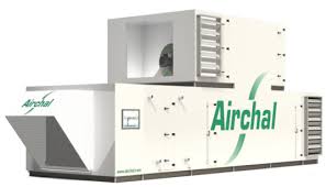
The requirements on a ventilation system are not always the same. In many applications, all that is required is a straightforward exchange of air, whereas in other applications the requirements can be very exacting with regard to temperature, humidity and purity of the air. Rosenberg air handling units in the Airbox series have a modular design and can be individually configured. In this way, the appropriate solution can be assembled using a kind of modular principle for each application in a quick and straightforward procedure. Both, in the high-tech area and for classic building technology, air handling units from Rosenberg deliver clean air at the right tempered room climate. Weather-proof and explosion-proof designs are possible, as well as TÜV certified hygiene variants. The units consist of a framework structure with double-skinned panels that have acoustic and thermal insulating properties. The individual modules for the filter, fan, heater, cooler, heat recovery, acoustic insulation as well as the frame materials, are assembled flexibly according to the customers‘ requirements.

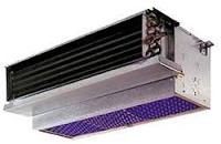
The F40 series is produced in a frameless design. The panels are screwed together from the outside so that the devices are smooth internal surfaces and are hence hygienically safe.
best central hvac units The air handling units Airbox A20, S40, S60, T60 are equipped with a framework construction made from aluminium or galvanised, rolled steel profiles and aluminium cast corner connectors or plastic corner connectors.
home air conditioner compressor coverIn the case of the Airbox A20, the double-skinned panels are insulated with non-combustible, sound and thermal insulating mineral wool.
ac unit for 1300 square foot houseThe Airbox S40, S60 and T60 air handling units are also filled with non-combustible, sound and heat insulating rock wool insulation.

In addition to galvanised steel panels and the framework construction, it is also possible to select coated steel, aluminium and stainless steel versions in our range. For modules with smaller dimensions, the base frame is manufactured in various heights (100, 300, 500 mm) using galvanised, folded steel sheet. Larger modules have a welded base frame (primed or galvanised). 3 mm aluminium profile 1,5 mm galvanised steelor stainless steel 1,5 mm galvanised steel 1,5 mm aluminiumand thermally decoupled The main factors which are important for the energy efficiency of an air handling unit are the air velocity in the profile unit face as well as the electric power consumption of the fan which is dependent on the air volume and pressure increase. In a combined air handling unit with heat recovery (HRU), the efficiency and pressure loss of the heat recovery must also be taken into account. We work in accordance with the statutory requirements of the German Energy Saving Ordnance (EnEV), as well as the requirements of the German AHU Manufactures Association (RLT) when selecting the parameters for air velocity, the electrical power consumption of the fans and the efficiency of heat recovery.
The criteria of the RLT energy efficiency label correspond to the standard DIN EN 13053 A1 (2011). This standard defines nine air velocity classes from V1 to V9, six heat recovery classes from H1 to H6 as well as six classes for the power consumption of fans from P1 to P6. The specific power consumption of a fan (SFP), installed in the air handling unit, is calculated as defined by the current DIN EN 13779. Air velocity class without thermal air treatment Air velocity class with air heating and / or heat recovery Air velocity class with additional functions Electric power consumption class Heat recovery classes (4,000 - 6,000 hours per year) > 1,6 to 1,8 > 1,8 to 2,0 > 2,0 to 2,2 > 2,2 to 2,5 > 2,5 to 2,8 > 2,8 to 3,2 > 3,2 to 3,6 The accuracy of the data output by our AHU selection software is regularly checked and certified by TÜV Süd, on behalf of the RLT association. For more information about the RLT energy efficiency label, refer to the AHU guideline 01 from the German AHU Manufactures Association (RLT).

Test certificate of energy efficiency labelFile format: .pdfFilesize: 632.69 kBThis is the eight of 20 steps in the in the Energy Management Action Programme (Energy MAP). Learn about Energy MAP and what it can do for your business. Quantifying energy use for each equipment category helps you to identify the large energy users, and prioritise these for early action. If you are implementing capital investments to deliver the savings, it is often necessary to justify these in terms of cost-benefit, which means that you must quantify overall energy use by a piece of equipment and the likely savings.This guide provides you with the formulae to calculate operating costs and savings, and discusses techniques to quantify energy use for different plant and equipment.Formulae to calculate annual electricity use and costFor each piece of equipment calculate annual electricity use and cost. You will need the three straightforward formulae provided below.Annual electricity use, expressed in kWh, depends on electrical power when on and run hours:There are a number of methods for establishing the power of equipment.

Their accuracy depends on the piece of equipment.Note that for a 3 phase load total power is the sum of the power for each phase (using above formula). If you don’t know what a 3-phase load is, have an electrician take the current readings.*Power [kW] = voltage [V] x current [Amp] x powerfactor / 1000 = 230 x current x 0.8 /1000 = 0.184 x currentIdentify the different types of lamps in use and their wattage. Wattage is usually written on the lamps, or you can ask whoever maintains the lamps. Then quantify the number of lamps of each type. You may find it helpful to break these up into zones, e.g. ground floor reception, ground floor offices, etc.To establish annual run hours for each zone consider how they are controlled and the occupancy hours.Note: for the purposes of simplicity, we have ignored control gear losses. If you know in what cases these apply, add 15% to electricity use.TIP: if you work late one night you will see what time the lights are actually switched off.

You will also develop a great insight into night-time operating characteristics: what plant and equipment is on and off. Compare this to your night profile.The IT manager should be able to tell you the number of PCs in use. Alternatively, find out the number of occupants and estimate what proportion of these have PCs.Power use by PCs varies depending on manufacturer, year, screen type, screen powersave settings and computer powersave settings. At this point, using an overall figure will be sufficiently accurate:Annual electricity use for one value PC with monitor in an average office, where the computer and monitor are switched off (using button) at night and both automatically go into standby mode after 20 minutes 160kWhAnnual electricity use for one value PC with monitor in an average office, where the computer and monitor are switched off (using button) at night, , - to do more accurate, site-specific calculations, go to this website and use the energy calculator.)For other office equipment – printers, photocopiers, fax, speakers, vending machines - either allow an additional 15% of the total annual electricity use for PCs, or count the number of each type and use the Energy Star online calculator.

The simplest approach is to find the distribution board supplying power to the IT room and take current readings for each circuit.Assume the load is broadly the same at night as during the day, annual electricity use = power x 8760 hours/yr.Note that UPS systems draw a small quantity of power when in standby mode. This can be established either by interrogating the UPS controls or taking an ammeter reading. Assume that this load is stable/continuous.Pumps are used for a variety of purposes: to circulate heating water, circulate chilled water for cooling, circulate hot water for washing, pressurise drinking water, and dispose of rainwater.To establish power use either take an ammeter reading (preferable) or use the nameplate. An efficient approach is to take ammeter readings for the larger pumps and accept nameplate for the smaller ones.Annual operating hours for each pump should be established by considering how it is controlled. Heating, Domestic Hot Water (DHW) and chillwater systems should all operate on time schedules or time switches.
A view must be taken on seasonal variations in run hours.Supply and extract fans, often contained in packaged air handling units, are required for respiration. They may also fulfil a heating/cooling role.An efficient approach is to take ammeter readings for the larger equipment and accept nameplate for the smaller ones.Annual operating hours for each fan should be established by considering how it is controlled and what the associated time schedules are.Small packaged air-conditioning units are proliferating. They are often referred to as DX (direct exchange) units, or split A/C units. Each unit has an indoor unit (evaporator) and outdoor unit (condenser). They are generally installed to provide cooling, but are generally capable of heating too.There are so many variables that affect electricity use that establishing annual electricity use can only be done accurately by logging/submetering electricity use over a long period. However, this is not practical.To establish power use take the nameplate rating.

This is generally on the side of the outdoor unit. If available, note “electrical input”, “cooling output” and “heating output”. If “electrical input” is not available, there may be some indication of Full Load Amps (FLA).Use your own judgement, based on the application, to establish the likely number of operating hours per year. In an IT room it will be on continuously, in an office it might only be used during office hours in hotter summer months.The unit will always draw a small quantity of power when it is on. However, it is only when the compressor is running that the nameplate power is drawn. As a rough indicator, assume that the unit draws its nameplate power for 50% of the time that it is on.Example:FLA = 6amps per phase=> Total Nameplate Power = 6 x .184 x 3 = 3.3 kWOn for 1000 hours per year=> Draws Nameplate Power = 1000 x 50% hours=> Estimated Annual Electricity = 3.3 x 500 = 1,650kWhThe other common sources of cooling are chillers. Again, there are so many variables that affect electricity use that establishing annual electricity use can only be done accurately by logging/submetering electricity use over a long period.

Our first preference is to log electricity use over a 1 or 2 week period and extrapolate this to annual use, making some allowance for seasonal variations.If this is not possible, then a similar approach to that outlined for air-conditioning units should be used. It is critical to evaluate if the chiller simply operates on a timeschedule throughout the year, or if there are controls in place to inhibit its operation in cool weather.Assessing energy use for catering is difficult to do accurately, particularly as electricity, gas, or a combination of both may be used for cooking.Our first preference is to use submeter readings, or log electricity use over a 1 or 2 week period and extrapolate this to annual use, making some allowance for seasonal variations.A rule-of-thumb approach is to allow 5kWh/meal. If gas is used for cooking, then 80% of this (4kWh/meal) will be gas, and the balance electricity.For other energy uses, use your judgement to establish which of the above techniques is most appropriate.

Get the total annual electricity use for each of the categories of equipment (lights, pumps, ventilation, etc.).Subtract each of these categories from the figure for total annual electricity use, established in Step 7. This balance represents a combination of miscellaneous users not quantified (e.g. security cameras, fire monitoring system) and any errors in your calculation. Ideally it should be less than 25% of the total.Use these values to create a pie chart.Fossil fuels, such as gas, are burned in boilers to generate heat. That heat is used for space heating and domestic hot water. The space heating component may in turn be split into heat loss through the building fabric and ventilation heat loss. Ventilation heat loss may be as a result of the controlled mechanical ventilation of a building and through uncontrolled ventilation including open windows, doors and unsealed fabric.Calculations of heat use associated with these different elements is specialised and beyond the scope of this document.