air handling unit pressure

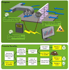
Air Handling Unit Transmitters Project Lead: Karen Lobo Sponsor: Physical Plant-Campus Services Project Theme: Energy Conservation & Efficiency Project Description: Install MS Magnesense Differential Pressure Transmitters on air handling units in eight campus buildings. These switches will notify PP-CS’s Energy Management System when filters are reaching the end of their life cycles and need to be replaced. Using the switches will end the current method of relying on scheduled replacement dates and human observation, which are often incorrect and lead to the replacement of filters that still have lifecycle remaining. Goals: Order and install new air filters only when EMS has been notified by the MS Magnesense Differential Pressure Transmitters. This project hopes to realize the extended life cycle of air filters for a time space of 50% greater than the current method. Savings include energy, human labor, purchase and transportation of new filters, and disposal and transportation of old filters.

Furthermore, data loggers installed at each location will measure Amp and voltage needed to calculate energy consumption and monitor decreased usage. This project will also help with LEED credit application and compliance with CalGreen code for indoor air quality. TGIF Blog Posts about Air Handling Unit Transmitters Project was delayed due to difficulty hiring a student intern and the project received TGIF approval for a timeline adjustment. Purchased the project equipment: 6 Differential Pressure Switches Data Loggers Filters and Conduit. 2 installed at California Hall. 3M vs. Filtrite (both mini pleated filters). Testing two different types of filters against each other to see which one has the longest life cycle - new filters will reduce labor costs, landfill waste, vehicle gas for traveling to the location. Using the Energy Management System to monitor pressure drop on filters on a monthly basis. 2 installed at Koshland Hall. Mini pleated vs. bag/ring combo filters.
Hired student intern Ace Haidrey. Stationary engineer Mike Schefers will work with Ace on the project; Mike will provide Ace with education, advising, and mentorship on energy and HVAC. Next Steps: Project will focus on installations at Bechtel Hall, as well as the on-going monitoring of the equipment results. Met with filter vendors and evaluated filters for the test sites. Walked Bechtel Hall to prep the site for installing the Differential Pressure Switches. 2 installed at Bechtel Hall. Filtrair vs Tridem filters. 1 installed at Barker Hall. Working to see if collaboration with Zero Waste Research Center is possible. Researching companies who will pick up used air filters for recycle. Future Plans: The project hopes to continue in the next academic school year, 2013-2014. The next steps for this project include the accrual of data in the next year for each of the buildings and to continue to monitor them throughout the year. Data to be collected:

Will measure the amplitude and voltage of filters, which will provide quantifiable metrics to calculate the energy consumption. Create charts and graphs illustrating the savings in dollar amounts. Create figures to represent the elongated lifecycles of the filters. Compare the filter price vs. the actual lifespan. The Green Initiative Fund (TGIF) provides funding for projects that reduce UC Berkeley's negative impact on the environment and make UC Berkeley more sustainable.
air handling unit valvesTGIF will allocate funds to projects that promote sustainable modes of transportation, increase energy and water efficiency, restore habitat, promote environmental and food justice, and reduce the amount of waste created by UC Berkeley.
ac dc power supply militaryPortions of the fund also support education and behavior change initiatives, student aid (via return to aid), and internships.
split unit ac power consumption
TGIF is supported by student fees and administered through a student-majority committee and a program coordinator.The requested URL /en/Certification_Programmes/Programme_Descriptions.php?lg=en&rub=03&srub=01&select_prog=RAHU was not found on this server. An alternative method for measuring air-handling unit static pressure following ASHRAE Standard 37: Scenario 1—horizontal ducts with elbows (RP-1581) Grant Wheeler & Michael PateGrant Wheeler, MS, is a Systems Engineer and a Graduate Student.Michael Pate, PhD, Life Member ASHRAE, is a Professor and Director. ASHRAE Standard 37 (ASHRAE 2005) describes the air-side testing setup for the indoor side (i.e., air-handling unit) of a residential air-conditioning or heat pump system for energy performance testing. Furthermore, ASHRAE Standard 37 requires a straight downstream duct that forms a vertical test section of a specified length based on the air-handling unit outlet geometry for measuring the outlet static pressure. A potential problem is that adding this duct to the unit may result in an overall test apparatus height that exceeds psychrometric test room dimensions.

One possible solution investigated in this project is to create a horizontal test section by the addition of an elbow placed after the unit. The air-handling unit outlet static pressure can then be measured in this horizontal test section, which has the same length requirements as that specified by ASHRAE Standard 37 for the vertical section. This horizontal duct orientation with an elbow is referred to as Scenario 1, while a second approach based on installing a passive resistive device at the air-handling unit outlet is referred to as Scenario 2, which is the subject of a second article. Experimental tests were performed on 2-, 3-, and 5-ton units, with a variety of elbow types and orientations located at the unit exit. Experiments were also performed on the same three units with vertical test sections as described in ASHRAE Standard 37 (i.e., baseline data). Comparisons of these test results showed that ASHRAE Standard 37 can be modified to reduce testing height restrictions by using a horizontal test section providing a right-angled elbow with double-thickness turning vanes and installed at the air-handling unit outlet in a specific orientation relative to the rotating blower.