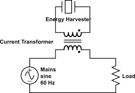
ac power supply circuits for energy harvesting

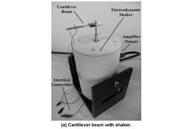
... but the URL you have requested was not found. To find what your are looking for please browse or search the ACM Digital Library. We apologize for this inconvenience. Please contact us with any questions or concerns regarding this matter:The requested URL /scielo.php?script=sci_arttext&pid=S1678-58782012000500006 was not found on this server.Equivalent circuit modeling of a piezo-patch energy harvester on a thin plate with AC–DC conversion B Bayik1, A Aghakhani1, I Basdogan1 and A Erturk2 Published 7 April 2016 • © 2016 IOP Publishing Ltd Smart Materials and Structures, As an alternative to beam-like structures, piezoelectric patch-based energy harvesters attached to thin plates can be readily integrated to plate-like structures in automotive, marine, and aerospace applications, in order to directly exploit structural vibration modes of the host system without mass loading and volumetric occupancy of cantilever attachments. In this paper, a multi-mode equivalent circuit model of a piezo-patch energy harvester integrated to a thin plate is developed and coupled with a standard AC–DC conversion circuit.
Equivalent circuit parameters are obtained in two different ways: (1) from the modal analysis solution of a distributed-parameter analytical model and (2) from the finite-element numerical model of the harvester by accounting for two-way coupling. After the analytical modeling effort, multi-mode equivalent circuit representation of the harvester is obtained via electronic circuit simulation software SPICE. Using the SPICE software, electromechanical response of the piezoelectric energy harvester connected to linear and nonlinear circuit elements are computed. Simulation results are validated for the standard AC–AC and AC–DC configurations. For the AC input–AC output problem, voltage frequency response functions are calculated for various resistive loads, and they show excellent agreement with modal analysis-based analytical closed-form solution and with the finite-element model. For the standard ideal AC input–DC output case, a full-wave rectifier and a smoothing capacitor are added to the harvester circuit for conversion of the AC voltage to a stable DC voltage, which is also validated against an existing solution by treating the single-mode plate dynamics as a single-degree-of-freedom system.
Usage and citation metrics Please see the page article level metrics in IOPscience for more information about the statistics available. Article usage data are updated once a week. Usage statistics are currently unavailable for this article at this time. The computer you are using is not registered by an institution with a subscription to this article. Please log in below. Find out more about journal subscriptions at your site. Purchase this article online By purchasing this article, you are accepting IOP's Terms and Conditions for Document Delivery. LTC2935 - Ultra-Low Power Supervisor with Power-Fail Output, Selectable Thresholds LTC3108 - Ultralow Voltage Step-Up Converter and Power Manager 950nA Input Quiescent Current (Output in Regulation – No Load) 450nA Input Quiescent Current in UVLO 2.7V to 20V Input Operating Range Integrated Low-Loss Full-Wave Bridge Rectifier Up to 100mA of Output Current Selectable Output Voltages of 1.8V, 2.5V, 3.3V, 3.6V
High Efficiency Integrated Hysteretic Buck DC/DC Input Protective Shunt – Up to 25mA Pull-Down at VIN ≥ 20V Wide Input Undervoltage Lockout (UVLO) Range Available in 10-Lead MSE and 3mm × 3mm DFN Packages
hvac unit online Designed for Automotive and Transportation Applications AEC-Q100 data available for specific packages
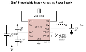
ac and heater maintenance The LTC®3588-1 integrates a low-loss full-wave bridge rectifier with a high efficiency buck converter to form a complete energy harvesting solution optimized for high output impedance energy sources such as piezoelectric, solar, or magnetic transducers.
how to fix a leaking air conditioning unitAn ultralow quiescent current undervoltage lockout (UVLO) mode with a wide hysteresis window allows charge to accumulate on an input capacitor until the buck converter can efficiently transfer a portion of the stored charge to the output.
In regulation, the LTC3588-1 enters a sleep state in which both input and output quiescent currents are minimal. The buck converter turns on and off as needed to maintain regulation. Four output voltages, 1.8V, 2.5V, 3.3V and 3.6V, are pin selectable with up to 100mA of continuous output current; however, the output capacitor may be sized to service a higher output current burst. An input protective shunt set at 20V enables greater energy storage for a given amount of input capacitance. Output Voltage (Switcher)UVLOQuiescent Current Selectable 1.8V, 2.5V, 3.3V or 3.6V Selectable 3.45V, 4.1V, 4.5V or 5V CAD Symbols and Footprints: The downloadable Zip file below contains the schematic symbol and PCB footprints. LTC3588-1 Footprints and Symbols For complete and up to date package information and drawings, please refer to our packaging page Part numbers ending in PBF are lead free. Solder plated terminal finish (SnPb) versions are non-standard and special terms and conditions and pricing applies if available.
Please contact LTC marketing for information.Part numbers containing TR or TRM are shipped in tape and reel or 500 unit mini tape and reel, respectivelyPlease refer to our general ordering information or the product datasheet for more details Package Variations and Pricing Buy Now • Request Samples * The USA list pricing shown is for BUDGETARY USE ONLY, shown in United States dollars (FOB USA per unit for the stated volume), and is subject to change. International prices may differ due to local duties, taxes, fees and exchange rates. For volume-specific price or delivery quotes, please contact your local Linear Technology sales office or authorized distributor. Linear Technology offers many demo boards free of charge to qualified customers. Contact your local sales office or distributor to inquire about a demo board. Certain demo boards are also available for sale via credit card on this website. Demo boards are for evaluation purposes only. It remains the customer’s responsibility to verify proper and reliable operation in the actual end application.
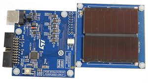
LTC3588EMSE-1 Demo Board | Piezoelectric Generator Power Supply ENERGY HARVESTING (EH) MULTI-SOURCE DEMOBOARD Energy Harvesting (EH) Multi-Source Demo Board with Transducers Click here to view our complete list of demo boards Designed for Automotive and Transportation Applications AEC-Q100 data is available for these specific part numbers. Please contact your local sales representative for more information regarding reliability reports or to inquire about parts that are not included. For more information, view our Automotive and Transportation page Battery Replacement for Industrial Sensors Standalone Nanopower Buck Regulator People Who Viewed This Product Also Viewed LTC3105 - 400mA Step-Up DC/DC Converter with Maximum Power Point Control and 250mV Start-Up LTC3330 - Nanopower Buck-Boost DC/DC with Energy Harvesting Battery Life Extender LTC3588-2 - Nanopower Energy Harvesting Power Supply with 14V Minimum VIN LTC3109 - Auto-Polarity, Ultralow Voltage Step-Up Converter and Power Manager
LT3652 - Power Tracking 2A Battery Charger for Solar Power LTC3108-1 - Ultralow Voltage Step-Up Converter and Power Manager LTC4071 - Li-Ion/Polymer Shunt Battery Charger System with Low Battery Disconnect LTC3331 - Nanopower Buck-Boost DC/DC with Energy Harvesting Battery Charger LTC3107 - Ultra-Low Voltage Energy Harvester and Primary Battery Life Extender Please login to your MyLinear account for notifications of datasheet updates, new document releases and LTspice model announcements for your favorite products. If you do not have a MyLinear account you may Sign Up Now. with questions and comments. LTspice® software is a powerful, fast and free simulation tool, schematic capture and waveform viewer with enhancements and models for improving the simulation of switching regulators. Click here to download LTspiceTo launch a ready to run LTspice demonstration circuit for this part: Step 1: If you have not installed LTspice on this computer, download and install LTspice