ac power supply schematic symbol

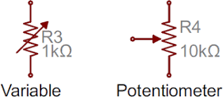
Are you ready for a barrage of circuit components? Here are some of the standardized, basic schematic symbols for various components. The most fundamental of circuit components and symbols! Resistors on a schematic are usually represented by a few zig-zag lines, with two terminals extending outward. Schematics using international symbols may instead use a featureless rectangle, instead of the squiggles. Variable resistors and potentiometers each augment the standard resistor symbol with an arrow. The variable resistor remains a two-terminal device, so the arrow is just laid diagonally across the middle. A potentiometer is a three-terminal device, so the arrow becomes the third terminal (the wiper). There are two commonly used capacitor symbols. One symbol represents a polarized (usually electrolytic or tantalum) capacitor, and the other is for non-polarized caps. In each case there are two terminals, running perpendicularly into plates. The symbol with one curved plate indicates that the capacitor is polarized.
The curved plate represents the cathode of the capacitor, which should be at a lower voltage than the positive, anode pin. A plus sign might also be added to the positive pin of the polarized capacitor symbol. Inductors are usually represented by either a series of curved bumps, or loopy coils. International symbols may just define an inductor as a filled-in rectangle. Switches exist in many different forms. The most basic switch, a single-pole/single-throw (SPST), is two terminals with a half-connected line representing the actuator (the part that connects the terminals together). Switches with more than one throw, like the SPDT and SP3T below, add more landing spots for the the actuator. Switches with multiple poles, usually have multiple, alike switches with a dotted line intersecting the middle actuator. Just as there are many options out there for powering your project, there are a wide variety of power source circuit symbols to help specify the power source.

Most of the time when working with electronics, you’ll be using constant voltage sources. We can use either of these two symbols to define whether the source is supplying direct current (DC) or alternating current (AC): Batteries, whether they’re those cylindrical, alkaline AA’s or rechargeable lithium-polymers, usually look like a pair of disproportionate, parallel lines: More pairs of lines usually indicates more series cells in the battery. Also, the longer line is usually used to represent the positive terminal, while the shorter line connects to the negative terminal. Sometimes – on really busy schematics especially – you can assign special symbols to node voltages. You can connect devices to these one-terminal symbols, and it’ll be tied directly to 5V, 3.3V, VCC, or GND (ground). Positive voltage nodes are usually indicated by an arrow pointing up, while ground nodes usually involve one to three flat lines (or sometimes a down-pointing arrow or triangle).

Schematic Symbols (Part 2)AC Input, 5V/3.3V2A Cascaded Power Supply Reference Design View the Important Notice for TI Designs covering authorized use, intellectual property matters and disclaimers. 22 Sep 2015 133 views
ge outside ac unit View All Technical Documents (4)
gree split air conditioner remote control manual The PMP4472 is a power reference design with a high AC input, 5Vout, followed by a DC isolated output of 3.3V at 2A.
average cost to replace a 2 ton ac unitIt implements a high efficiency controller UCC28740 to provide 5V bus voltage and a step-Down Converter TPS54228.The design achieves good line and load regulation as well as good dynamic response and low output ripple voltage.

Isolated Flyback and Buck converter 2 outputs include 5V Bus voltage Good line and load regulation Low output ripple voltage TI's Standard Terms and Conditions for Evaluation Modules apply. PMP4472.1(Output Voltage 1)PMP4472.2(Output Voltage 2) Vin (Min) (V)1985 Vin (Max) (V)2425 Vout (Nom) (V)53.3 Iout (Max) (A)1.52 Output Power (W)7.56.6 Isolated/Non-IsolatedIsolatedNon-Isolated Input TypeACDC TopologyFlyback- Quasi ResonantBuck- Synchronous Order samples, get tools and find more information on the TI products in this reference design. Design Kits & Evaluation Modules Adjustable Precision Shunt Regulator 4.5V to 18V Input, 2-A Synchronous Step-Down Converter with Eco-mode™ View Design Kits & Evaluation Modules Constant-Voltage, Constant-Current Flyback Controller Using Opto-Coupler Feedback Offline and Isolated DC/DC Controllers and Converters As a member ofmy.TI you can join theTI E2E™ Community where you can ask questions, share ideas and collaborate with fellow engineers and TI experts

Contents are provided "AS IS" by the respective TI and Community contributors and do not constitute TI specifications. Engage in the Community Broadband RF/IF & Digital Radio Visit the TI WikiStandard Electrical Symbols For Electrical Schematic Diagrams Free Download Electrical Diagram Software with More than 2000 Electrical Symbols Most of the electrical symbols can be changed in their appearance, styles and colors according to users' requirements. Electrical symbols are used to represent various electrical and electronic devices in a schematic diagram of an electrical or electronic circuit. The following table lists some basic electrical symbols in our electrical drawing software. The electrical symbols for most major basic electrical components can be found However, each electrical component may have numerous possible representations. The electrical symbols can vary from country to country nowadays, but are to a large extent internationally standardized.

Some electrical symbols become virtually extinct with the development of new technologies. cases where there is more than one common electrical symbol, we have tried to give an This group of symbols is located in the Engineering category in the Available Templates list. After you start Edraw, click the icon of Basic Electrical Symbols to open the stencil including this kind of shapes. The stencil panel is opened on the left along with a blank canvas on the right. Drag the shape you need directly onto the canvas. Instead, you can click its icon and then click on the location where you want to place it. After you add shapes on the drawing page, they are selected by default. So you can resize them by dragging the green selection handles. A double sided arrow shows the direction to which you can move the mouse. Move the shape when a four-direction arrow appears. software, you can use the action button to choose the right electrical symbols with one click. It shows when the shape is selected or when the pointer is over the shape.