ac to dc power supply block diagram

Power Supply: AC/DC, Isolated, w/ PFC, > 90W Power Supply: AC/DC, Isolated, w/ PFC, > 90W TI Designs & reference designs Application notes & user guides Selection & solution guides Product bulletin & white papers Blogs & authored articles Similar end equipment solutions AC/DC Isolated Power Supply with PFC > 90WAn AC/DC Isolated Power Supply with PFC > 90W is used to convert the AC power lines to an isolated regulated DC output for powering notebook computers and other equipment. Typically, these operate with a wide-range of AC inputs from 85V to 265V AC (for worldwide source voltage compatibility). Generally, there is only one output in the 12V to 20V range which is compatible with most battery packs. Typically, above approximately 90W, Power Factor Correction (PFC) is used. One of the most desirable attributes of an AC/DC supply is high efficiency. To realize this, Zero Voltage Switching is incorporated. Specifically, this Active Clamp and Reset technique features the benefits of Zero Voltage Switching, simplicity and few components.
EEPROM Emulation With the TMS320F28xxx DSCs Flash Programming Solutions for the TMS320F28xxx DSCs TMS320F281x Boot ROM Serial Flash ProgrammingThe challenges faced by AC/DC power supply developers today are achieving high power factor, low THD, and high efficiency across line and load conditions, high power density or reduced size, high reliability, and low system cost. Advanced power topologies such as interleaved PFC, bridgeless PFC, phase-shifted full-bridge DC/DC, LLC resonant DC/DC, and ZVS PWM DC/DC are commonly employed in today's designs addressing these needs. Most AC/DC power supplies use dual PWM controllers, a PFC controller and a DC/DC controller. TI's Continuous Conduction Mode PFC controller achieves CCM control with fewer circuit components reducing BOM cost. Interleaved PFC controllers cater well for higher power and higher density form factor applications. The interleaving offers both input and output ripple current cancellation allowing smaller EMI filter, boost inductor and bulk capacitor.

TI's PWM DC/DC controller portfolio includes controllers for the Flyback, LLC Resonant Bridge, Phase Shifted Full Bridge, and Active Clamp Forward Topologies commonly found in server AC/DC designs. The Flyback controller uses a frequency modulation scheme that optimizes efficiency across the output power range while also providing unmatched 125mW no load power consumption. The LLC resonant half bridge controller offers 'zero voltage switching' ZVS of the power MOSFETs, a bounded operating frequency range and minimal external components improving both efficiency and overall system cost. The Active clamp forward controller family offers improved efficiency over single switch forward converters by both reducing the stress and allowing a lower voltage main switch MOSFET and by using the active clamp to recycle the magnetizing energy of the main transformer. The Phase shifted full bridge controller remains to be the industry's controller of choice for higher power applications as it offers ZVS and other features that helps reduce stress of MOSFETs and increase efficiency.

The family of UCC27xxx MOSFET drives includes a complete range of single and dual low-side MOSFET drivers ranging from 2A to 9A sink and source. They are available in complimentary, inverted and non-inverted varieties.
ac vs heat pump price TI's Integrated Hot Swap Power Controllers are optimized for nominal -48V systems.
power supply ac to dc 12 voltThe devices provide load current slew rate control and peak magnitude limiting.
air handling unit valve package Most of the Hot Swap Controllers have digital interface for precise programming and monitoring and also have Power good and fault outputs. Other high-performance analog parts are also available to provide critical system functions and features such as sensor feedback, isolation, communication transceivers.

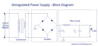
As illustrated in view B of figure 4-1, the first section is the TRANSFORMER. steps up or steps down the input line voltage and isolates the power supply from the power line. RECTIFIER section converts the alternating current input signal to a pulsating direct current. you proceed in this chapter you will learn that pulsating dc is not desirable. For this reason a FILTER section is used to convert pulsating dc to a purer, more desirable form of dc voltage. The final section, the REGULATOR, does just what the name implies. It maintains the output of the power supply at a constant level in spite of large changes in load current or input line voltages. Now that you know what each section does, let's trace an ac signal through the power supply. point you need to see how this signal is altered within each section of the power supply. Later on in the chapter you will see how these changes take place. In view B of figure 4-1, an input signal of 115 volts ac

is applied to the primary of the transformer. The transformer is a step-up transformer with a turns ratio of 1:3. You can calculate the output for this transformer by multiplying the input voltage by the ratio of turns in the primary to the ratio of turns in the secondary; therefore, 115 volts ac 3 = 345 volts ac (peak-to- peak) at the output. Because each diode in the rectifier section conducts for 180 degrees of the 360-degree input, the output of the rectifier will be one-half, or approximately 173 volts of pulsating dc. section, a network of resistors, capacitors, or inductors, controls the rise and fall time of the varyingconsequently, the signal remains at a more constant dc level. You will see the filter process more clearly in the discussion of the actual filter circuits. The output of the filter is a signal of 110 volts dc, with ac ripple riding on the dc. The reason for the lower voltage (average voltage) will be explained laterThe regulator maintains its output at a constant 110-volt dc level, which is used by the