hvac heat pump diagram

If you are looking for a better understanding of heat pump thermostat wiring, here is an example of a typical electronic type heat pump control wiring which is located inside your house. There are many types of electronic thermostat in the market these days, hence please check that the type of thermostat that you are using can be replaced with the newer ones. A new programmable heat pump thermostat can be purchased for less than $50. Normally, an electronic thermostat in the United States is powered by a 24V AC power supply which comes from a 110V/24V power transformer. If you are not sure, always refer to the operating manual of your thermostat in your house before attempting to do any trouble shooting or replacement work. As always, if you are not trained to handle electrical equipment, please get a qualified technician to do it.It is always a good idea to take a picture of the current heat pump thermostat wiring before you start removing them.In heat pump system, there are at least 8 wires that need to be connected to the thermostat for proper operation.
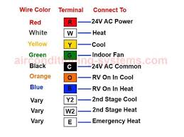
Heat pump thermostat wiring - A typical wire color and terminal diagram As shown in the diagram, you will need to power up the thermostat and the 24V AC power is connected to the R and C terminals. The color of wire R is usually RED and C is BLACK. C is known as the common terminal. These two connections will ensure that there is power to the thermostat that you are operating. The Y terminal is where the signal to the cooling air conditioner signal is connected. This terminal will call for the need to cool the room when the set temperature is lower than the room temperature. The G terminal is connected to the indoor fan which circulates the air in the room.The reversing valve is a device that reverses the flow of the refrigerant in the piping system. In most cases, the reversing valve is energized when running cool mode. However, there are instances where the reversing valve is off when running cool mode. Therefore, it is important the check the manufacturer's specifications of the heat pump system that you are using before you can do a proper connection to the thermostat.

The O terminal is used when the system that you are using has a reversing valve (or four way valve) which is turned on when running cooling mode. If the reversing valve is turned on when running heat mode, you will need to connect the reversing valve to B terminal. Only one connection is active at any one time, that is either O or B terminal is used but not both.In some equipment, there is a 2nd stage cooling that helps to increase the cooling capacity of the room. In this case the terminal Y2 is usually used. The color of the wire vary. Sometimes, there is a 2nd stage heating where additional heating is provided to supplement the primary heating system. This is usually installed in regions where extreme winter occurred. In this case the terminal W2 will be present.Some thermostat may have a feature called Emergency Heat where when set, it will shut off the heat pump. It will then turn on the strip heat which becomes the primary source of heating. This feature should only be used for a while as the energy cost is usually higher than a heat pump system.

The terminal used is E.Look out for the following features that are incorporated in most modern programmable heat pump thermostat.
replacing outdoor ac unit Back To Heat Pump Thermostat Wiring Home Page
ac unit emergency heatThe links below are to current Bard product wiring diagrams.
lg room air conditioner problems Second law is followed if energy in is not perfectly(Some energy converted to heat). The bigger the temperature difference between cold and hot, the more electrical energy is needed. (Like air conditioners on a hot Air conditioners make us of special liquids which absorb heat as they change from a liquid to a gas and release the heat again as they change from a gas to a liquid. COLD region = house

HEAT PUMP = evaporator, compressor, condenser and liquidWhere can you find wiring diagrams for York heating and cooling systems? provides wiring diagrams for much of York's line of heating and cooling systems. The website publishes resources for services, repair and product information of a variety of products, including detailed product guides for rooftop, blower-coil, heat pump and fan units by York. What reviews do York air-conditioning systems receive? What wiring diagrams does Lennox provide? , there is an accompanying technical specifications chart that lets consumers see how the units in the diagrams differ from one another. The charts offer precise specifics on such variables as heating capacity, starting current, air flow level and the units' physical dimensions. The wiring diagrams feature one diagram to represent the wiring scheme for several units. Each diagram refers back to the technical specifications chart's physical dimensions specifications to allow a reader to visualize her particular York heating or cooling unit properly.
Where can you buy parts for York air conditioners?Each site offers a variety ... How does one figure out how to fix a York furnace? A person can figure out how to fix a York furnace by doing some troubleshooting, such as looking at the thermostat, the power and filter. Some of these rep... When should a York HVAC unit be replaced? The parts that make up the various HVAC units produced by York have an average life span of 10 to 20 years. Certain parts, such as the heat exchanger on th... Where can you buy York air conditioners? York air conditioners are only available through consultation with an authorized York dealer, which are found using the Get A Quote From Your Local York De... How do you repair a ceiling fan? What are some techniques for basic electrical wiring and splicing? How do you sign up for the LIHEAP heating assistance program? Where can you buy inexpensive Danby dehumidifiers? Why would a furnace blow cold air?